Note.
At the later stages of the development of designs of gravitational-magnetic engines, it was found and shown that it is possible to do without the levitation of magnets and, accordingly, without the need to use magnets in the mutual repulsion. (See sections 22. Appendix 7 and 23. Appendix 8)
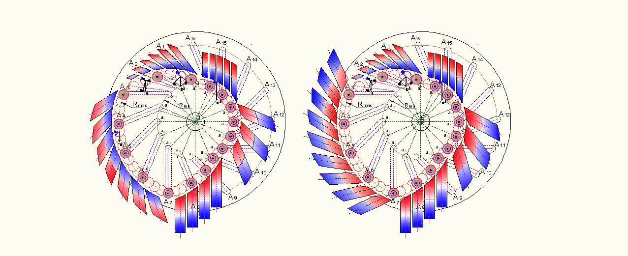
In the sector a14 – O – a16 (Fig. 2), where the impact of gravity on the centers of gravity movable loads exerts a force inhibiting rotation, the orientation of the permanent magnets of stator realizing attraction of the magnets of movable loads is possible, and, at the correct choice of the length of air gap between the pole surfaces of the interacting magnets, it may prove useful.
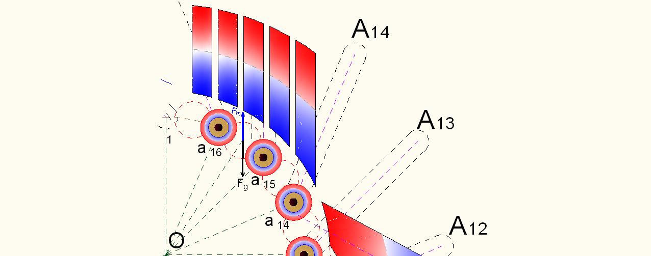
Fig. 36
In the Fig. 36 is shown the placement of the stationary magnets near the trajectory movement of the cylindrical loads in the sector a14 – O – a16. Orientation of the permanent magnets of stator realizes the attraction of the magnets of movable loads. In the figure is shown the interaction of couple vectors: vector of attraction magnets (Fm) and vector of the gravitational impact (Fg), attached to the center of gravity in one of the possible points of the location of movable load. The air gap between the pole surfaces interacting magnets should be such as to preclude full attraction of the magnets. Otherwise, conditions will be created for the occurrence of friction between the surfaces of the magnets, which will lead to a strong braking of the rotation. That is, vector Fm should be slightly smaller of the vector Fg. For example, it is desirable that the magnitude of the vector Fm was (75 ... 80)% of the magnitude of the vector Fg.
As a result, the impact of gravitation to the movable loads passing this sector of rotation, that creates here the torque directed clockwise, that is, inhibits rotation to the needed direction, will be significantly weakened.
In the sector a1 – O – A2 (Fig. 2) the impact of gravitation on the centers of gravity of the movable loads exerts a force which facilitates rotation to the needed direction. However, the contribution of the impact of gravitation into the net torque on the motor shaft is rather small. The cause of minor magnitude of this contribution is in relatively small values of the lever arms of rotation arising for the centers of gravity of the movable loads during their movement into this area of rotation. In this sector, it is possible and advisable to orientate stationary magnets on attraction of the movable loads.
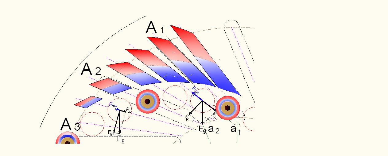
Fig. 37
In the Fig. 37 is shown an example of such orientation. Into this area of rotation also must be excluded the total attraction the magnets of the movable loads to the surfaces of the stator magnets. In this figure are pointed out vector diagrams for two points of possible location of the centers of gravity of the movable loads. With the help of these diagrams is explained the interactions vectors of attraction magnets (Fm+) with components of the vectors of the gravitational effects (Fg), that is, with vectors Fg+ and Fg−. The symbol “+” means that the vector facilitates to the rotation (in the desired direction, i.e., counter clockwise), but the symbol “−” means — impedes. The movable loads, in this section of track, are moving by inertia along the inclined paths respective to them. The stationary magnets contribute to this movement and accelerate it, due to their orientation for attraction. As a result the offset of the centers of gravity of the movable loads is accelerated to the left from the vertical line, passing through the axis of rotation of the engine (through the point “O” in the Fig. 2), herewith, the lengths of the lever arms of rotation, emanating from the centers of gravity of the respective loads, are increased faster. This increases the contribution of the gravitational impact in the net torque. Mass of stationary magnets used in this sector of rotation may be required significantly lesser than in the embodiment with using magnets in repulsion mode.
In the sector A3 – O – A7 (Fig. 2) the impact of gravitation on the centers of gravity of the movable loads exerts a force which facilitates rotation to the needed direction. Here the movable loads, passing this section of track, are at the maximum distance from the rotor rotation axis (their centres of gravity move along the trajectory of a circumference whose radius is equal to Rmax). And in this case the movable loads, due to influence of gravity, provide the greatest value of the contribution into the net torque on the motor shaft. Into this sector of rotation it is also possible to orientate the stationary magnets for attraction.
In the Fig. 38 is shown proper arrangement of the stationary magnets near this sector of rotation.
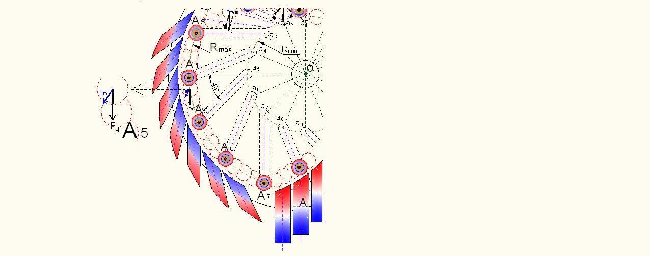
Fig. 38
In Fig. 38 is shown the interaction between the vectors of the gravitational and magnetic impacts (Fg and Fm) which are attached to the center of gravity of a movable load in one of its possible positions in the path of movement into this sector. In this sector of rotation is no danger of complete attraction magnets of the movable loads to the pole surfaces of the stationary magnets, since here the edges of walls of the inclined paths for the wheels of loads must prevent that. However, at too large force of attraction of the magnets movable loads to the surfaces of the stationary magnets the inhibitory effects are possible. Optimum interaction of the magnets should be selected during the experimental testing. Evidently, that such orientation of stationary magnets would create additional rotational force on this section of movement of the loads.
In the sector a11 – O – a14 (Fig. 2) the use of stationary magnets in attraction mode is not seems be possible. Consideration of the Fig. 39 shows that at this orientation of the stationary magnets the attraction of the movable loads into this sector of the moving will lead to a shift of their centers of gravity towards the Rmax . Herewith, the lengths of lever arms of rotation of the corresponding loads will increase. But since the gravity actualizes an inhibitory impact on the loads moving in this sector of rotation, it will reduce the net torque of the motor shaft additionally.
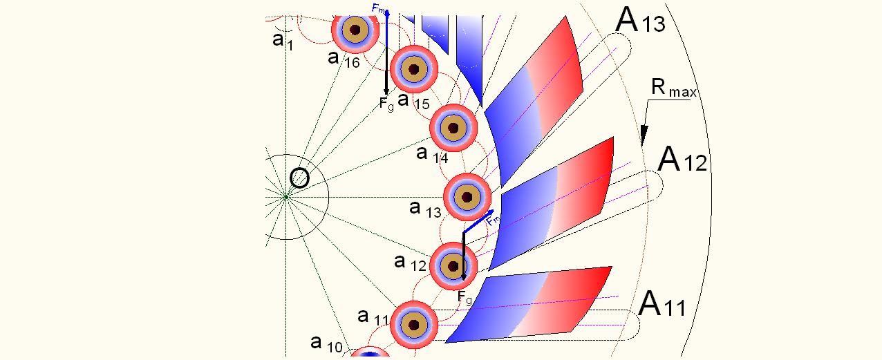
Fig. 39